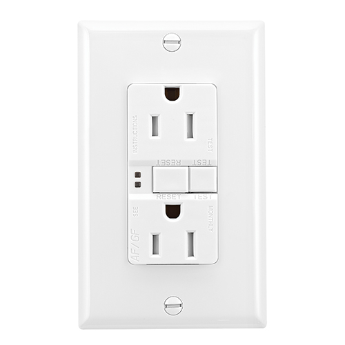
To wire a gfci circuit breaker see this link and wire a gfci switch combo at this link. Connect the line cables bare copper or green wire directly to the grounding terminal on the gfci.
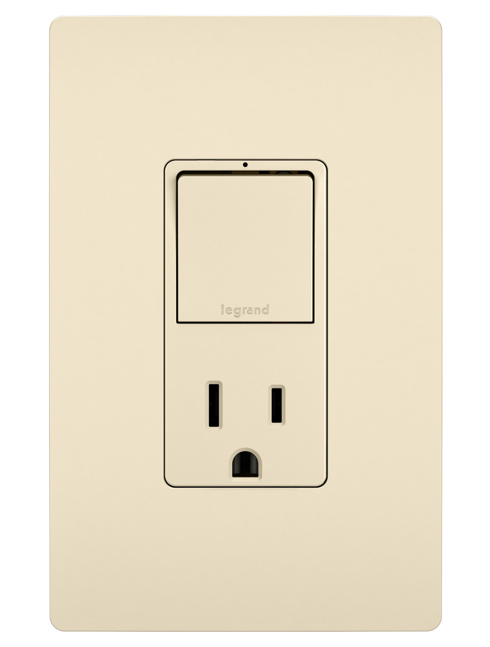
Does a afci receptacle work without a ground connection.

Cooper gfci wiring diagram. With levitons extensive assortment of combination devices you can fill a one gang space with two switches a switch and receptacle even a switch and gfci. I ns ertba dfuly tightenscrewfirmly clock wise23ofthe wayaroundscrew wire 78in ch 2. Trsgf15 line art with dimensions figure 4.
Wiring diagrams figure 3. Z wave plus wireless collection arrive home to a well lit house with our easy to use and install wireless lighting controls powered by z wave plus. From sensor guide lights to multi.
This diagram illustrates wiring a gfci receptacle and light switch in the same outlet box a common arrangement in a bathroom with limited space. Leviton gfci receptacle wiring diagram wiring diagram is a simplified good enough pictorial representation of an electrical circuitit shows the components of the circuit as simplified shapes and the capacity and signal connections together with the devices. Wiring for a switch and gfci receptacle in the same box is also shown.
Wiring a gfci outlet with switched garbage disposal. For a box with no grounding terminal diagram not shown. Select from multiple styles and.
Let the change of the season and fall colors inspire you to update and decorate your home with residential wiring devices in an assortment of colors and styles. Does a gfci receptacle work without a grounded wired. Here the gfci outlet the switch and disposal are all protected from ground faults.
Description amps volts color suffix trsgf15 nema 5 15r duplex self test gfci back side wire 15 125 a b bk gy la rb sg v w trsgf20 nema 5 20r duplex self test gfci back side wire. Tamper resistant self test gfci receptacles back side wire catalog no. Wire connector line cable brings power to the gfci this white wire is hot only when used to feed power to a switch black electrical box yellow sticker remains in place to cover the load terminals white aboutwireconnections.
What is does the amber light on your gfci indicate. Is it possible to wire a receptacle upside down. Wiring a gfci outlet and a light switch.
Do you offer a combination switch and receptacle that has a small indicator light on the switch. Loosen the silver and brass terminal screws on the line side of the outlet. Refer to the diagram above about wiring gfci receptacles for additional help.
The white wire connects to the white terminal silver the black wire connects to the hot terminal brass connect the grounding wire only if there is a grounding wire. This diagram illustrates the wiring for a cooper gfci combo switch device to control a garbage disposal. If more than 1 black and 1 white conductor are in the electrical box also loosen the load side silver and brass terminal screws.
 Unique Cooper Gfci Wiring Diagram Diagram Diagramsample
 Cooper Wiring Diagram Machine Learning
 Cooper Wiring Diagram Machine Learning
 Unique Cooper Gfci Wiring Diagram Diagram Diagramsample
 Cooper Wiring Diagram Machine Learning
 Cooper Gfi Receptacle Wiring Diagram Gfci Outlet Wiring Line
 Cooper Gfci Wiring Diagram Wiring Diagram Third Level
 Aff6d Cooper Gfci Schematic Wiring Wiring Resources
 Cooper Gfci Outlet Wiring Diagram Dmsimage Net
How To Wire A Gfci And Light Switch Fuckmywallet Co
 Cooper Wiring Diagram Automotive Wiring Schematic
 Gfci Wire Diagram Tips Electrical Wiring
141395 Leviton Switch Schematic Combo Wiring Diagram
 Wiring Diagrams For Leviton Bination Switch Gfci Tips
Combination Gfci Schematic Wiring Diagram Wiring Diagram
 Cooper Gfi Receptacle Wiring Diagram Gfci Outlet Wiring Line
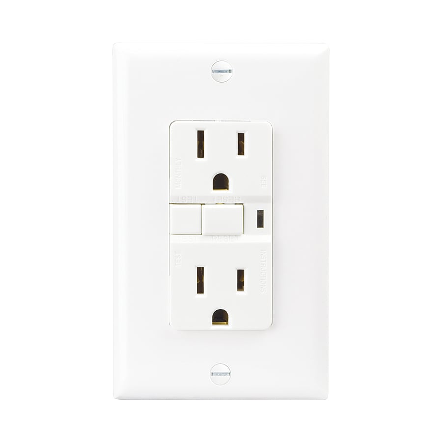 Wrg 4669 Gfi Plug Wiring Diagram
Cooper Gfci Wiring Diagram Wiring Diagram Third Level
 Cooper Gfi Receptacle Wiring Diagram Gfci Outlet Wiring Line
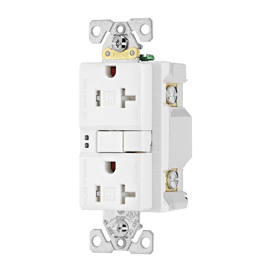 20a 125v Cooper Wiring Diagram Wiring Schematic Diagram
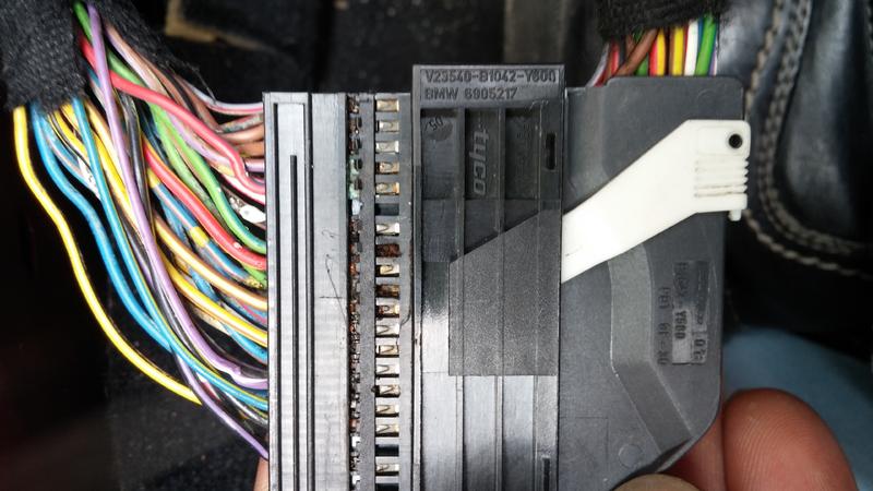 Cooper Wiring Diagram Automotive Wiring Schematic
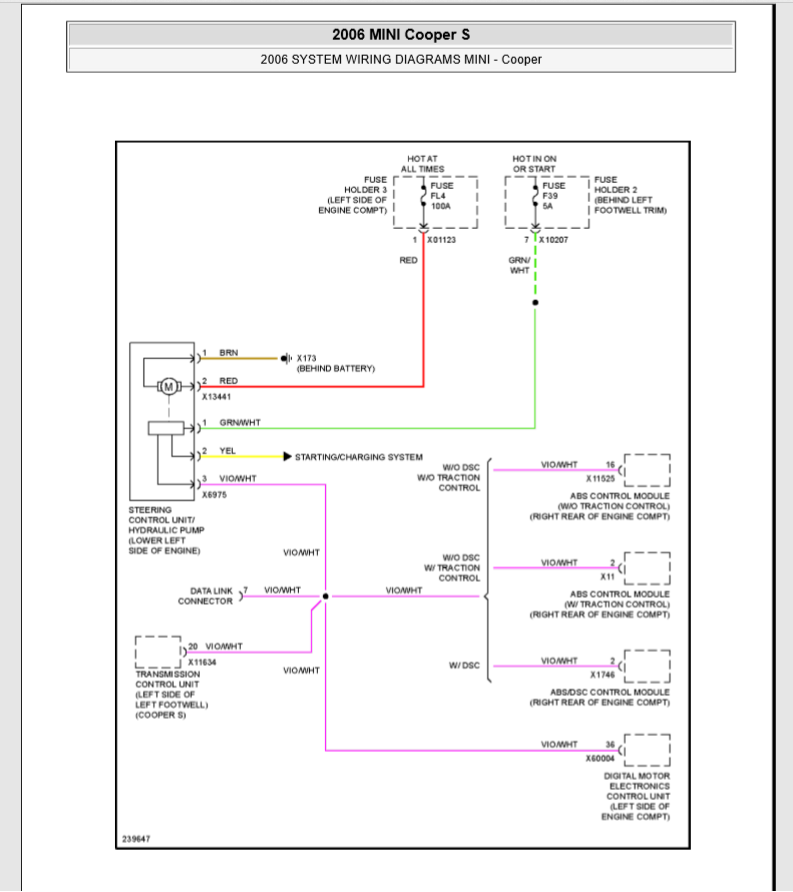 Cooper Wiring Diagram Automotive Wiring Schematic
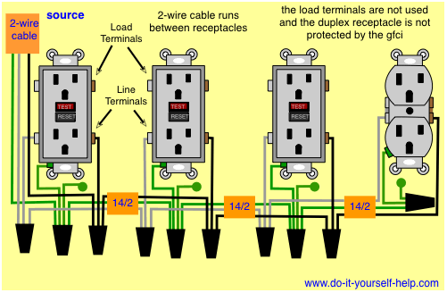 Gfci Wire Diagram Tips Electrical Wiring
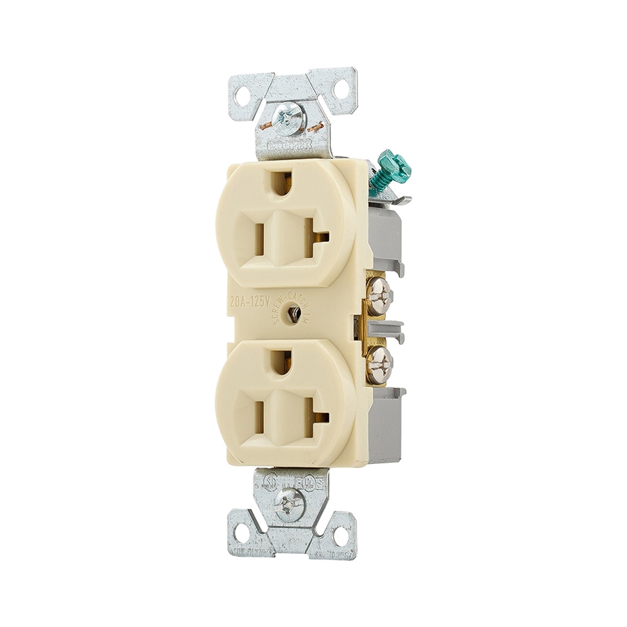 5315a Cooper Gfci Wiring Diagram Wiring Library
 Cooper Gfi Receptacle Wiring Diagram Gfci Outlet Wiring Line
 Leviton Presents How To Install A Combination Device With Two Single Pole Switches
 Unique Cooper Gfci Wiring Diagram Diagram Diagramsample
 Cooper Wiring Diagram Machine Learning
 Cooper Wiring Diagram Automotive Wiring Schematic
 Cooper Gfi Receptacle Wiring Diagram Gfci Outlet Wiring Line
066b Cooper Gfci Schematic Wiring Wiring Library
 Cooper Wiring Diagram Machine Learning
 Cooper Wiring Devices Twrsgf20w North Coast Electric
 Wiring Diagram Outlets 101warren
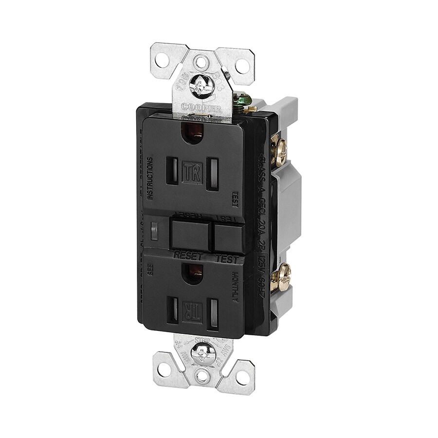 Gfci Outlet Diagram Best Collections Of Diagram Wiring
 Gfci Wiring Diagram Wiring Diagram General Helper
 6 Wire Gfci Schematic Diagram Wiring Diagram Cloud
 How To Install A Ground Fault Circuit Interrupter Gfci Outlet Plug
 Cooper Wiring Diagram Automotive Wiring Schematic
 Cooper Gfi Receptacle Wiring Diagram Gfci Outlet Wiring Line
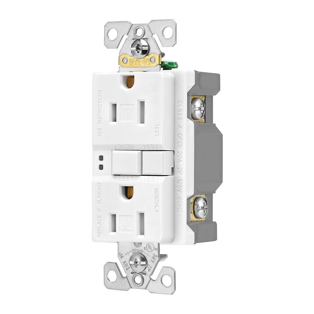 Eaton Gfci Self Test 15a 125v Tamper Resistant Duplex Receptacle With Standard Size Wallplate White
How To Wire Cooper 277 Pilot Light Switch
 Unique Cooper Gfci Wiring Diagram Diagram Diagramsample
Gfci Wire Diagram Tips Electrical Wiring
 Cooper Wiring Diagram Machine Learning
 020ec Cooper Gfci Switch Combo Wiring Diagram Wiring Library
 Unique Cooper Gfci Wiring Diagram Diagram Diagramsample
 Cooper Wiring 9566trsws Receptacle Gfci Tr St 15amp 2p3w Ws
How To Wire Cooper 277 Pilot Light Switch
 Cooper Wiring Diagram Automotive Wiring Schematic
 Cooper Wiring Devices Diagrams Auto Electrical Wiring Diagram
Cooper Gfi Receptacle Wiring Diagram Gfci Outlet Wiring Line
 How Do I Wire A Gfci Switch Combo Home Improvement Stack
 Cooper Wiring Diagram Machine Learning
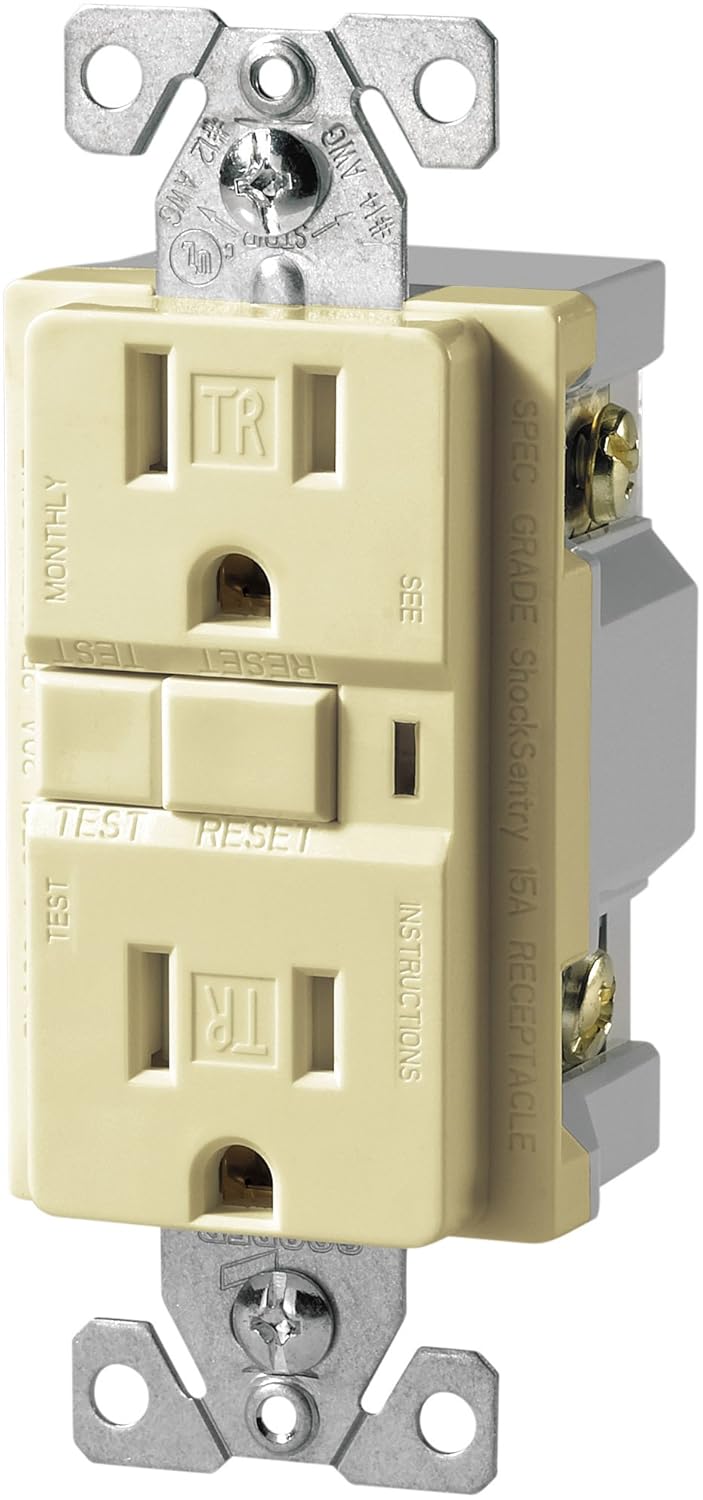 Cooper Gfi Receptacle Wiring Diagram Gfci Outlet Wiring Line
 Cooper Wiring Diagram Automotive Wiring Schematic
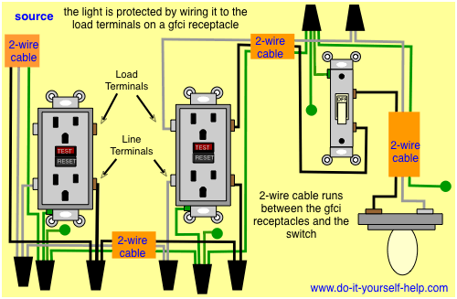 Gfci Wiring Diagram Wiring Diagram General Helper
Hubbell Wiring Device Kellems Gf20wlabulk North Coast Electric
Cooper Wiring Diagram Machine Learning
 Gfci Wiring Diagram Wiring Diagram General Helper
Gfci Wire Diagram Tips Electrical Wiring
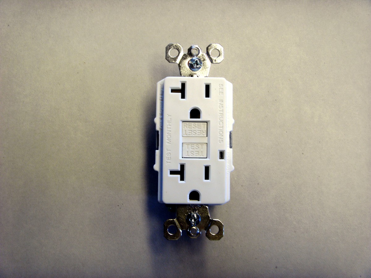 How To Wire Electrical Outlets Diy Receptacle Wiring

How To Wire Cooper 277 Pilot Light Switch
 Gfci Schematic Diagram Basic Electrical Wiring Theory
 Wrg 0325 1967 Vw Beetle Fuse Box Wiring Diagram
 Leviton Presents How To Install An Electrical Wall Outlet
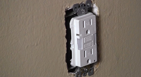 How To Install A Gfci Outlet The Home Depot
How To Install And Troubleshoot Gfci
:max_bytes(150000):strip_icc()/metal-countertop-and-electrical-outlet-95445753-57ffb9c65f9b5805c27e3ff3.jpg) Line Or Load With Gfci Connection
Line Or Load With Gfci Connection
 4 Wire 220 Volt Wiring Diagram Wiring Diagram General Helper
 Wiring 3 Way Switch Diagram Wiring Diagram Database
 Cooper Gfci Wiring Diagram Wiring Diagram Schemes
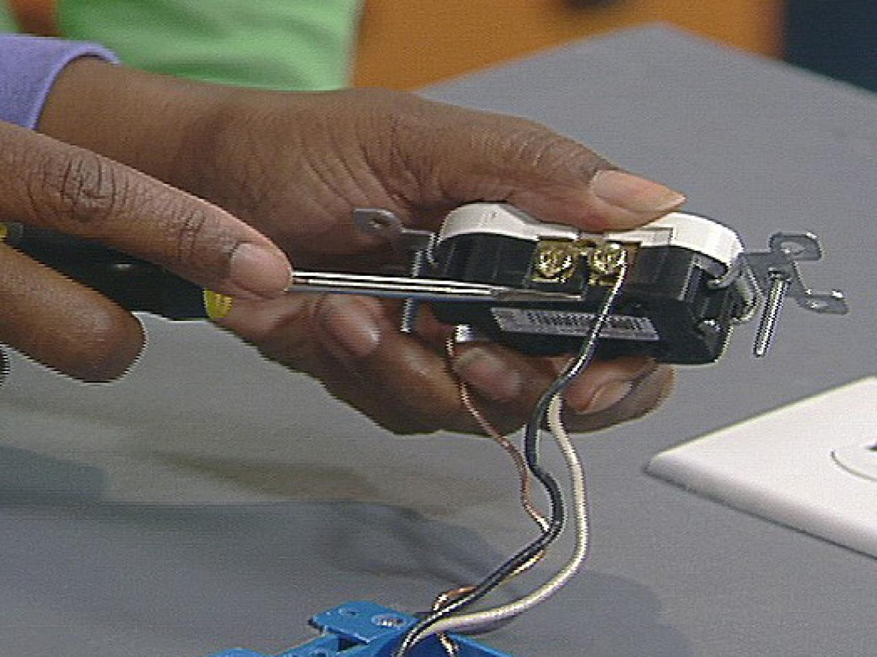 Install A Gfci Outlet How Tos Diy
 4 Wire 220 Volt Wiring Diagram Wiring Diagram General Helper
Solved What Color Wires Go To Power Switch And Circuit Fixya
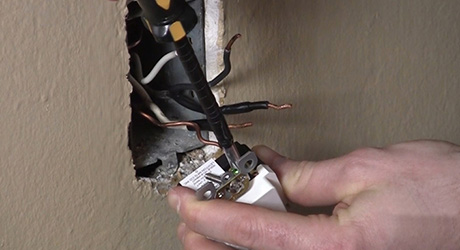 How To Install A Gfci Outlet The Home Depot
Wiring Diagram For 30 Amp 125 Volt Rv Receptacle Wiring
 Leviton Presents How To Install Smartlockpro Afci Gfci Outlet
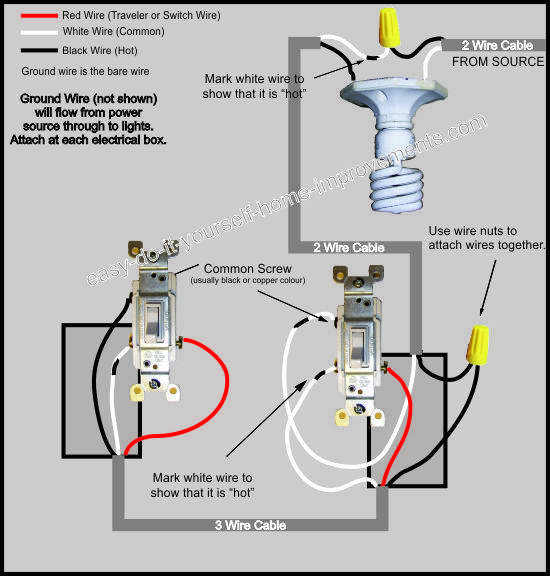 Wiring 3 Way Switch Diagram Wiring Diagram Database
 Aff6d Cooper Gfci Schematic Wiring Wiring Resources
 Wiring A Gfci Outlet With Diagrams Pro Tool Reviews
 Wiring Diagram Switch Schematic Combo Tips Electrical Wiring
 Power Receptacle Wiring Wiring Diagram General Helper
 Wiring A Gfci Outlet With Diagrams Pro Tool Reviews
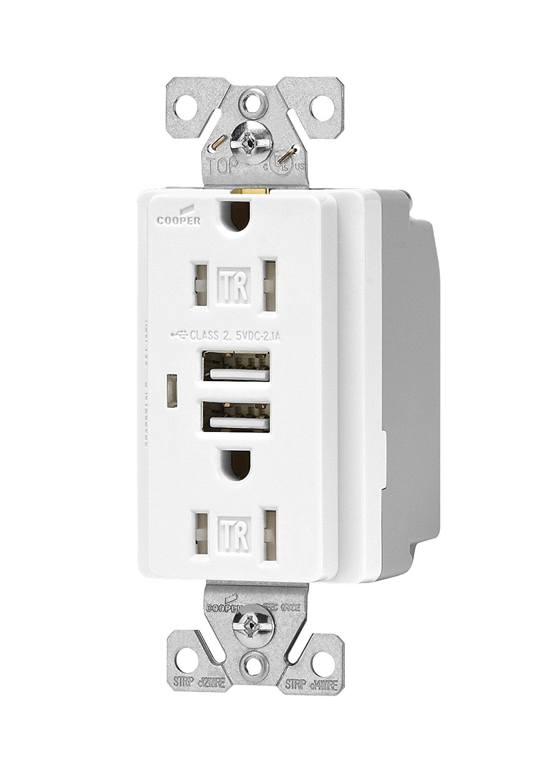 Tr7745w Combination Usb Charger With Tamper Resistant
 How To Install A Gfci Receptacle
45dfb Cooper Gfci Switch Combo Wiring Diagram Epanel
A9f30 Cooper Gfci Wiring Diagram Epanel Digital Books
 Bridget Webster Bridget6365 On Pinterest
 Cooper Electric Official Website
 B382a8 Cooper Gfci Switch Combo Wiring Diagram Epanel
 How To Install The Leviton Combination Switch And Tr Receptacle
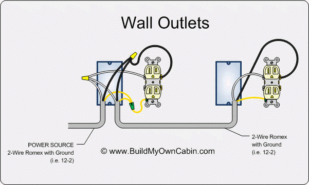 Power Receptacle Wiring Wiring Diagram General Helper
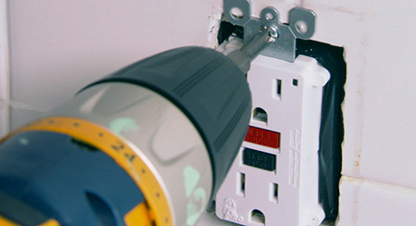 How To Install A Gfci Outlet The Home Depot
How To Wire Cooper 277 Pilot Light Switch

